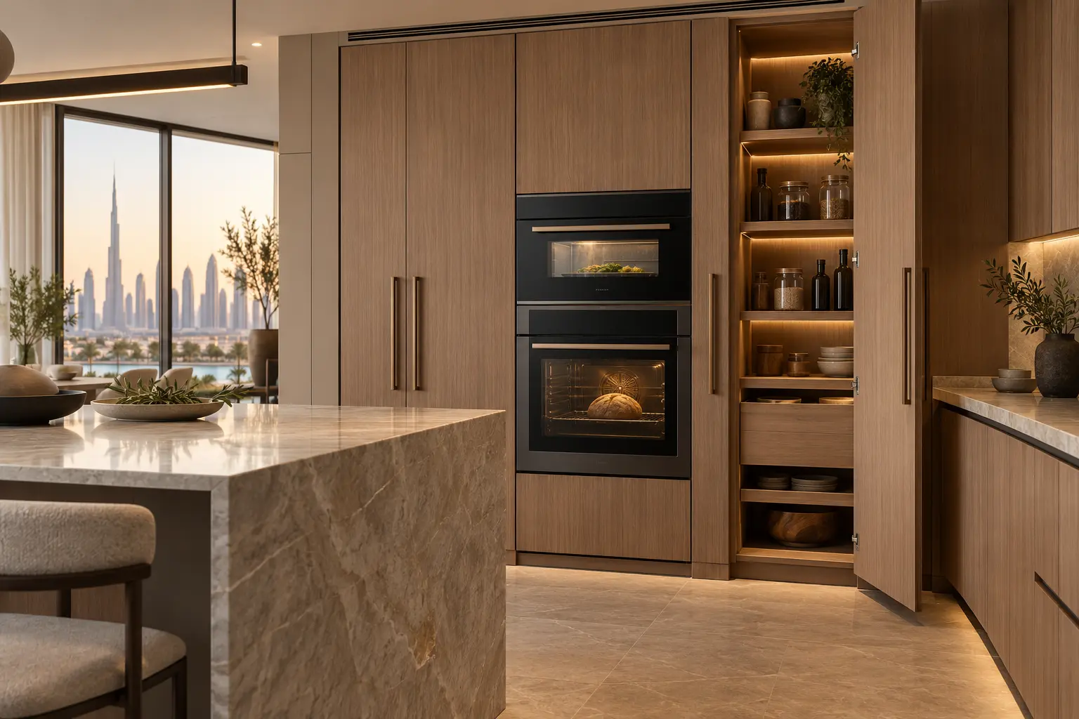
Direct answer: design the cabinet around the exact appliance data
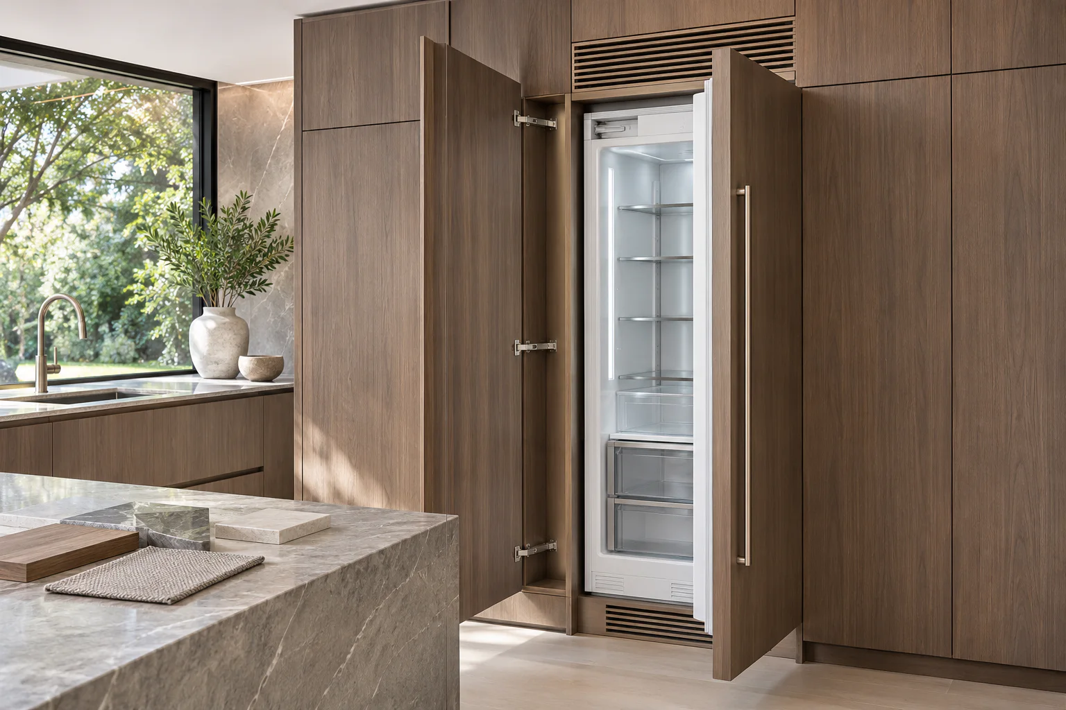
A useful refrigerator brief should confirm the exact regional model, installation manual, appliance and niche dimensions, door or custom-panel system, hinge side, ventilation inlet and outlet, electrical and water requirements where applicable, levelling access, adjacent clearances, finished floor condition, delivery route and future removal path. It should show the appliance and neighbouring doors in open positions. Cabinet manufacture should not start from a generic fridge space or catalogue width. Integrated and freestanding models manage air, panels and door movement differently, and even closely related products can require different openings.
Use a six-point appliance coordination check
Review model identity, niche, airflow, door geometry, services and serviceability. Model identity locks the correct manual and regional specification. Niche covers clear width, height, depth, squareness and floor. Airflow traces the inlet, path and outlet without relying on a decorative void. Door geometry checks hinge, panel, handle and adjacent collisions. Services locate accessible power and any water connection without obstructing installation. Serviceability proves that the appliance can be levelled, maintained and removed. A cabinet can pass five checks and still fail as a complete installation, so record all six before release.
Verify the current model and manual
Record the full model code, market, supplier, manual revision and whether the product is integrated, built-under or freestanding. Obtain the manufacturer’s installation drawing rather than relying on a retailer summary or a previous model. Bosch states that installation methods and measurements vary by model and directs users to model-specific instructions. Its published refrigerator guidance includes stated ventilation openings for the examples shown, but those figures must not be copied to a different appliance. If the owner has not selected the model, keep the cabinet on hold or define a documented shortlist whose requirements all fit the proposed design.
Trace the complete ventilation path
Show where air enters, passes the appliance and exits. Confirm the required free area after decorative grilles, plinth slots, mesh or joinery details are included. Check that skirting, flooring, stored objects and adjacent panels cannot block the route. Calculate free area from the actual proposed grille data rather than its outside dimensions, and record who verifies it. Coordinate the path with any dust filters or removable screens specified by the appliance maker, including the access needed for cleaning. DEWA consumer guidance has highlighted adequate ventilation behind appliances such as refrigerators; the exact configuration remains a manufacturer and specialist decision. Do not create hidden recirculating pockets or assume that an open cabinet back is sufficient. Keep heat-producing equipment and tall-unit arrangements coordinated against the selected manufacturers’ instructions rather than using a standard visual composition.
Planning example
Planning example: a kitchen elevation shows an integrated refrigerator beside a pantry pull-out and a wall return. The first cabinet drawing uses the nominal appliance width but does not show the custom panel opening. The exact manual reveals a required ventilation path and hinge geometry that would make the panel handle meet the wall before full opening. The designer adds the correct side allowance, revises the filler, coordinates the base and upper ventilation openings and confirms the socket position and removal route. This fictional scenario demonstrates the review; it is not an installation detail for a real appliance.
Check door swing, panels and adjacent cabinets
Draw the refrigerator door at the opening angles needed for normal access and internal drawer removal. Include the decorative panel thickness, handle projection, hinge action, side fillers and nearby walls or tall doors. Check whether a pantry pull-out, oven handle, room door or island edge conflicts. For custom-panel models, confirm panel size, weight, fixing pattern and reveal from the exact manual. A flush elevation can conceal significant movement geometry. Review the toe-kick and floor junction with the door open, and verify that baskets, shelves and ice or water components can be removed for normal service. Also coordinate the top and side finish pieces so they can be removed where the service method requires it, without dismantling unrelated cabinets.
Checklist before cabinet manufacture
Review the final appliance schedule against the cabinet drawing and installation manual. Mark a hold wherever supplier information, services or panel data remains provisional.
- Confirm the exact regional model and current installation manual
- Verify niche width, height, depth, squareness and finished floor
- Trace ventilation inlet, airflow path and outlet
- Check free area through grilles, plinths and decorative panels
- Draw appliance and adjacent doors in required open positions
- Confirm panel size, weight, hinges, fillers and reveals
- Coordinate accessible power and water where applicable
- Verify delivery, levelling, maintenance and removal access
- Require a new review for any appliance substitution
Limitations and qualified installation
This brief does not design electrical circuits, water connections, cabinet structure, fire protection or the appliance installation. Those tasks require the manufacturer’s current instructions and qualified kitchen, electrical and plumbing professionals. Model availability, manuals and regional specifications can change after design. The final supplier confirmation should therefore precede cabinet release. Do not modify an appliance, grille, cord, plug, hinge or cooling path to make a mismatched unit fit. If site dimensions or the delivered model differ, stop and re-coordinate rather than trimming the cabinet or concealing the conflict.
Next step: create a signed appliance interface sheet
Place the model code, supplier confirmation, manual reference, niche drawing, ventilation route, door-swing study, panel data, service points and removal sequence on one interface sheet. Have the kitchen designer, cabinet maker and relevant services representatives close their items before the fabrication drawing is approved. Add the date availability was confirmed and a substitution rule that requires the same review again. At delivery, compare the appliance label with the approved code before unpacking or altering cabinetry. During installation, preserve photographs of the ventilation path and accessible services before cover panels are closed. Retain the manual and interface sheet at handover so future replacement begins with a reliable record of what the cabinet was designed to receive.
Sources & further reading
Make this useful for your project.
A review of your property and priorities can turn general guidance into a defined brief.
Explore our servicesDiscuss your project