Direct answer: freeze the elevation, interfaces and sequence before measuring
A splashback brief should settle material and thickness, extent, pattern direction, joint strategy, edge treatment, socket and switch positions, penetrations, hob and sink interfaces, sealant lines, under-cabinet lighting, wall preparation and installation sequence. It should identify who measures, who approves the slab or batch, and who owns substrate readiness. Worktop templating is a dimensional milestone, not the right time to discover an undecided outlet or uneven wall. Issue a dimensioned elevation for every run and connect it to the cabinet, appliance, electrical and lighting information. A coordinated brief lets the fabricator price real cut-outs and joints while the electrician and cabinet maker work to the same approved geometry.
Choose the material as a wall system
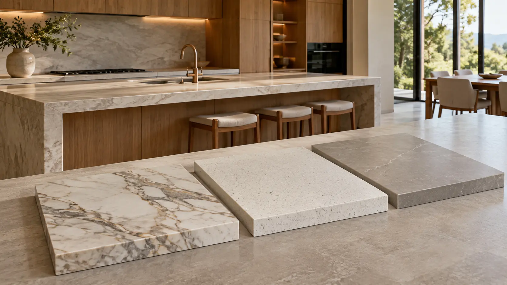
Large-format sintered surface, engineered surface, natural stone, tile, glass and metal each create different thickness, joint, backing, edge and cleaning requirements. Review the proposed product's current technical information and intended application rather than relying on a sample alone. Consider stain exposure, heat zone, impact at sockets, maintenance, repairability and how the material terminates beneath cabinets or at open ends. Natural variation and veining may require slab layout approval. Thin cladding still needs an appropriate substrate and fixing method. Product suitability does not eliminate the need for competent fabrication and installation. The specification should name the product or performance basis, finish, thickness, batch or slab approval process, and required manufacturer-compatible installation system.
Draw the complete elevation, not just the visible rectangle
Mark finished worktop level, underside of wall cabinets, extractor or hood, shelves, end panels, window reveals and every transition to paint or another material. Show whether the splashback continues behind removable appliances, beneath the hood and around returns. Dimension outlets from fixed datums and show faceplate size, orientation and grouping; a centre point is not enough when a cut-out must fit precisely. Coordinate taps, boiling-water units, dispensers and wall-mounted accessories. If the design uses book-matched or continuous veining, overlay the intended panel breaks. Open ends need a deliberate edge or return, not a raw decision made on site after cutting.
- Finished levels and cabinet undersides
- Panel extents and returns
- Outlet faceplate dimensions
- Penetrations and accessories
- Pattern direction and panel breaks
- Transitions to adjacent finishes
Coordinate the hob, sink and lighting zones
The cooking zone needs appliance-specific clearances and a finish appropriate to the installation conditions. Do not copy a generic distance from another kitchen; use the current appliance and product instructions and have the responsible professionals coordinate ventilation, power or gas and surrounding materials. At the sink, detail the worktop-to-wall junction, tap clearance, window or sill interface and sealant access. Under-cabinet lights need a profile location that does not expose glare, clash with sockets or cast an uneven beam across a strongly textured surface. Decide driver access and switching before the cabinets close. These three zones concentrate most of the service and maintenance interfaces, so they deserve enlarged details.
- Appliance-specific cooking clearances
- Sink and tap access
- Worktop-to-splashback junction
- Light profile and glare control
- Driver and control access
Planning example
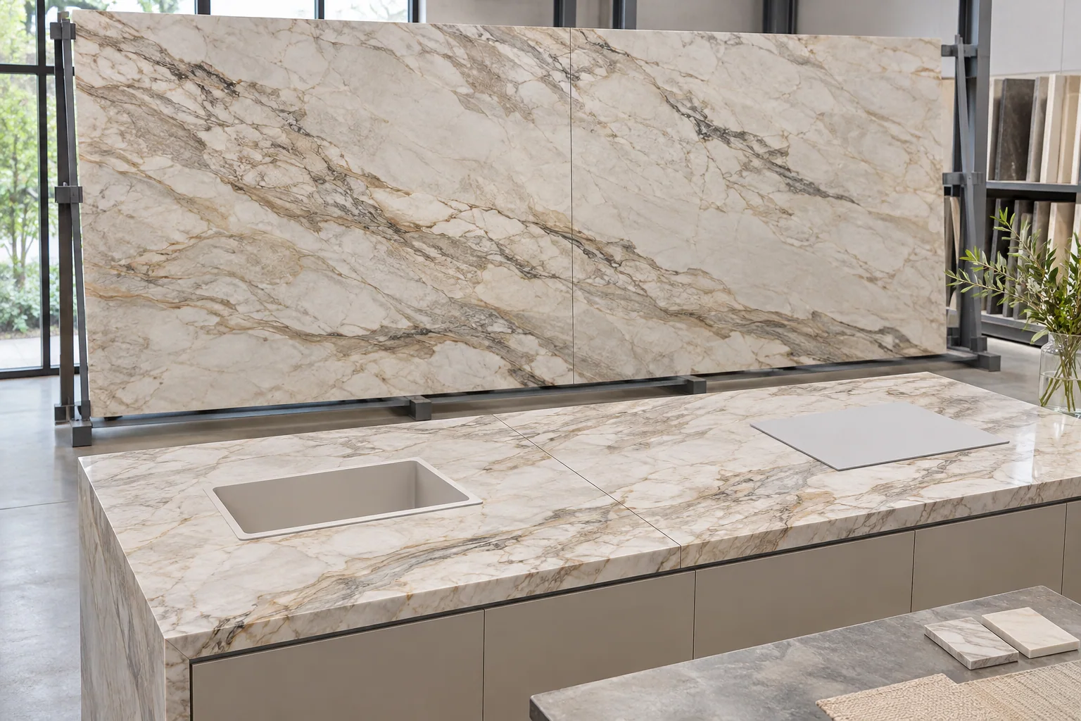
A kitchen uses a veined sintered worktop with a full-height matching splashback. The first elevation shows two double outlets but not their faceplate dimensions, and the hood model changes after cabinet approval. Before templating, the team issues a revised elevation using the installed cabinet and appliance datums. One outlet is shifted away from a prominent vein and a panel joint; the hood width and lower edge are fixed; the splashback divides at a low-visibility line; the sink return and open end receive enlarged details. The fabricator photographs the selected slab layout and records cut-outs. The electrician verifies back boxes before fabrication, while the installer confirms wall preparation and compatible fixing and sealant products. The result depends on coordination, not last-minute trimming.
Set a readiness gate for templating and fabrication
Create a signed readiness checklist. Base and wall cabinets that control dimensions should be installed, level, fixed and accepted. Relevant appliances, sinks, taps and accessories should be final selections with current technical drawings available; items affecting cut-outs may need to be on site according to the fabricator's requirements. Wall conditions must be inspected and the treatment of irregularities agreed. Electrical and lighting positions should match the approved elevation. The slab, batch, pattern direction and seam plan should be approved. Record who can authorise a change after measurement and what happens if site conditions move. Without this gate, measurement becomes a snapshot of an unfinished decision rather than a reliable basis for fabrication.
- Cabinets fixed, level and accepted
- Final appliance and accessory data
- Verified outlets and lighting
- Approved material and layout
- Agreed substrate preparation
- Formal control of post-template changes
Limitations and installer responsibilities
This guide does not provide fabrication dimensions, electrical instructions, gas work or an installation method. Those tasks belong to competent contractors following the actual product and appliance documentation, project design and applicable requirements. Substrate condition, movement, heat, moisture and material format can change the correct adhesive, joint and support strategy. Manufacturer manuals may give minimum joints or sealant guidance for a named product; do not transfer those figures to a different material. Existing walls can conceal services, so penetrations require appropriate checks. Confirm building or authority requirements where applicable, and never approve a visually clean detail that compromises safe access, ventilation or maintenance.
- Follow the selected product manual
- Use competent fabrication and electrical trades
- Check concealed-service risk
- Keep appliance ventilation and access
- Inspect completed joints and sealant
Checklist and next step
Before inviting the template visit, circulate the approved splashback elevations to the cabinet maker, fabricator, electrician, appliance supplier and lighting installer. Ask each party to confirm its interface rather than assuming silence means acceptance. The next step is a joint site readiness review using the installed kitchen and current product data. Photograph the datums and outlets, mark unresolved points, and postpone fabrication if a critical decision is still open. Once approved, lock the elevation and manage every later alteration through a written change record. That small discipline protects expensive panels, keeps veining and joints intentional, and gives the installer a buildable surface rather than a collection of competing site decisions.
- Approve material, extent and pattern
- Dimension every outlet and penetration
- Resolve hob, sink and lighting details
- Confirm wall and cabinet readiness
- Approve joints, edges and returns
- Control all changes after templating
Sources & further reading
Make this useful for your project.
A review of your property and priorities can turn general guidance into a defined brief.
Explore our servicesDiscuss your project